Car Brake Pad Dynamometer – Type B
Application:
The brake is one of the important components for safe driving of a car, and its performance has a significant impact on the driving safety and power performance of the car. Usually, brake performance is tested according to the testing standards set by authoritative institutions. The general testing methods include small sample testing and inertial bench testing. Small sample tests are used to simulate brake dimensions and shapes, resulting in low accuracy but relatively low cost. They are commonly used for grading friction materials, quality control, and the development of new products.
The brake dynamometer is the most authoritative test in brake quality inspection, which can truly reflect the working characteristics of the brake and has gradually become the mainstream of brake quality inspection. It can test brake systems in a controlled environment that mirrors the real world.
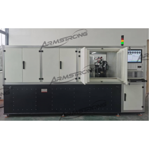
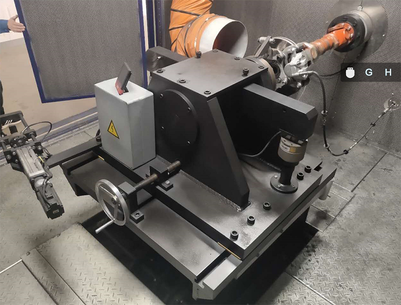
The Dynamometer test of automobile brakes is a simulation of the braking process of automobiles, which tests the braking efficiency, thermal stability, lining wear, and strength of the brakes through bench tests. The current universal method in the world is to simulate the braking conditions of a brake assembly using mechanical inertia or electrical inertia, in order to test its various performance. This split type dynamometer is designed for brake testing of passenger cars.
Advantages:
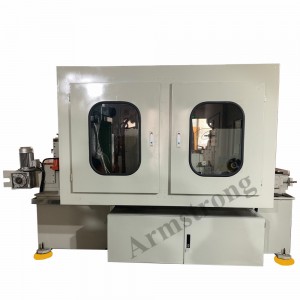
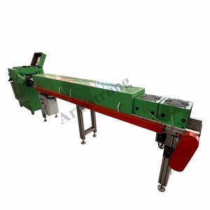
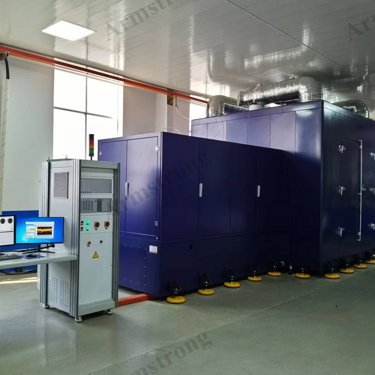
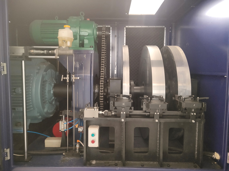
1.1 The host is separated from the test platform to minimize the impact of host vibration and noise on the test.
1.2 The flywheel is positioned with the conical surface of the main shaft, which is convenient for disassembly and stable operation.
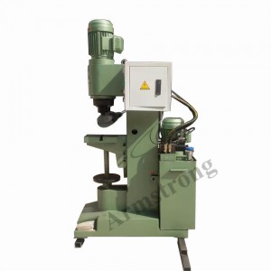
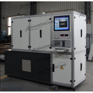
1.3 The bench adopts servo electric cylinder to drive the brake master cylinder. The system operates stably and reliably with high pressure control accuracy.
1.4 The bench software can execute various existing standards, and is ergonomically friendly. Users can compile test programs by themselves. The special noise test system can run independently without relying on the main program, which is convenient for management
1.5 Executable test standards: AK-Master, SAE J2522, ECE R90, JASO C406, ISO 26867, GB-T34007-2017 test and so on.
Product Detail
|
Main Technical parameters |
|
|
Main engine |
The split structure, the main body and the test platform are separated |
|
Motor power |
200 KW (ABB) |
|
Motor type |
AC frequency speed regulation motor, independent air-cooled |
|
Speed range |
0 - 2000 rpm |
|
Constant torque range |
0 to 990 rpm |
|
Constant power range |
991 to 2000 rpm |
|
Speed control accuracy |
± 0.2%FS |
|
Speed measurement accuracy |
± 0.1%FS |
|
Overload capacity |
150% |
|
Motor speed controller |
ABB 880 series, power: 200KW, unique DTC control technology |
| Inertia system | |
|
Test bench foundation inertia |
Around 10 kgm2 |
|
Min. Mechanical inertia |
Around 10 kgm2 |
|
Dynamic inertia flywheel |
80 kgm2 * 2+50kgm2 * 1= 210kgm2 |
|
Max. Mechanical inertia |
220 kgm2 |
|
Max. Electrical analog inertia |
40 kgm2 |
|
Analog inertia range |
10-260 kgm² |
|
Analog control accuracy |
Max. Error ±1gm² |
|
|
|
Maximum brake pressure |
20MPa |
|
Maximum pressure rise rate |
1600 bar/sec |
|
Pressure control linearity |
< 0.25% |
|
Dynamic pressure control |
Allows the input of programmable dynamic pressure control |
| Braking torque | |
|
The sliding table is equipped with a load sensor for torque measurement, and the full range |
5000Nm |
|
Measurement accuracy |
±0.1% FS |
|
|
|
Measuring range |
0 ~ 1000℃ |
|
Measurement accuracy |
± 1% FS |
|
Compensation line type |
K-type thermocouple |
|
Rotating channel |
Passage through collector ring 2 |
|
Non rotating channel |
Ring 4 |
Partial technical parameters