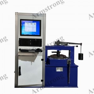
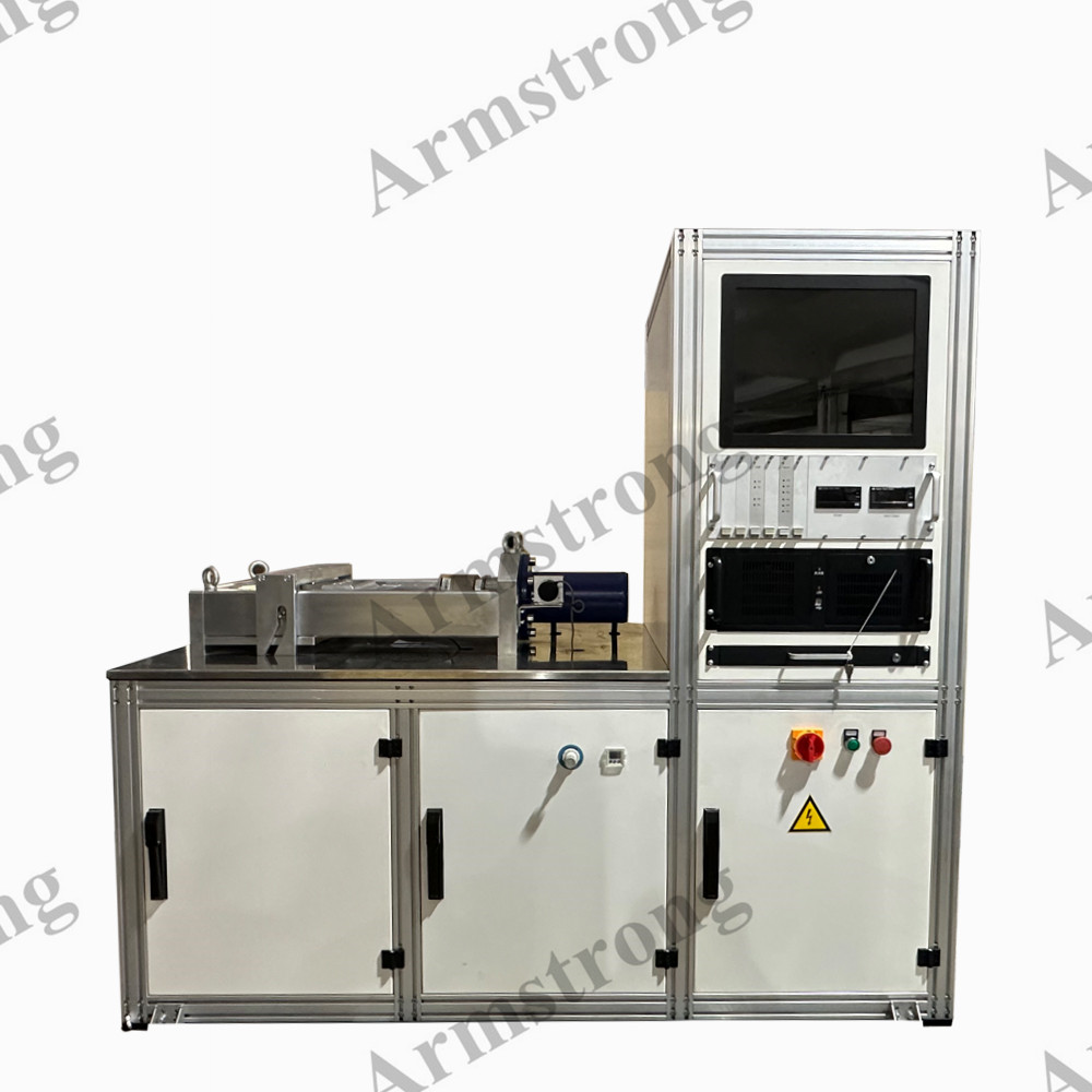
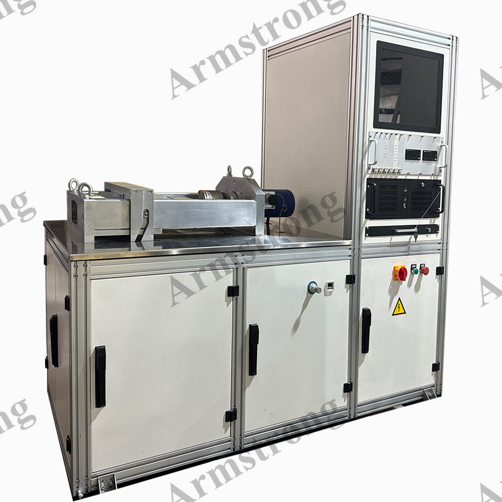
Shear strength test machine
1. Main Functions:
The Shear Strength Test Machine is used to measure and test the bond strength between brake pad friction materials and metal parts.
It mainly applied to the disc brake pad (also bonded shoe assembly - user selected item).
2. Easy operation steps:
A. Start the software
B. Click the "Parameters" button to set the parameters required by the system
C. Click the "Oil Pump" button to start the hydraulic pump.
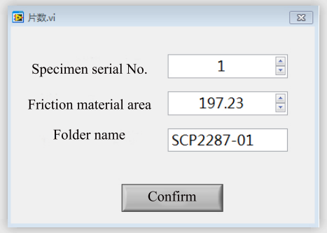
D. Click the "START" button, enter the parameters and confirm in the pop-up window (as shown in Figure), and the cutting process will be completed automatically.
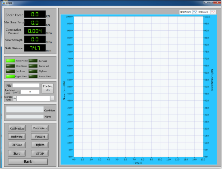
Simple Software Interface
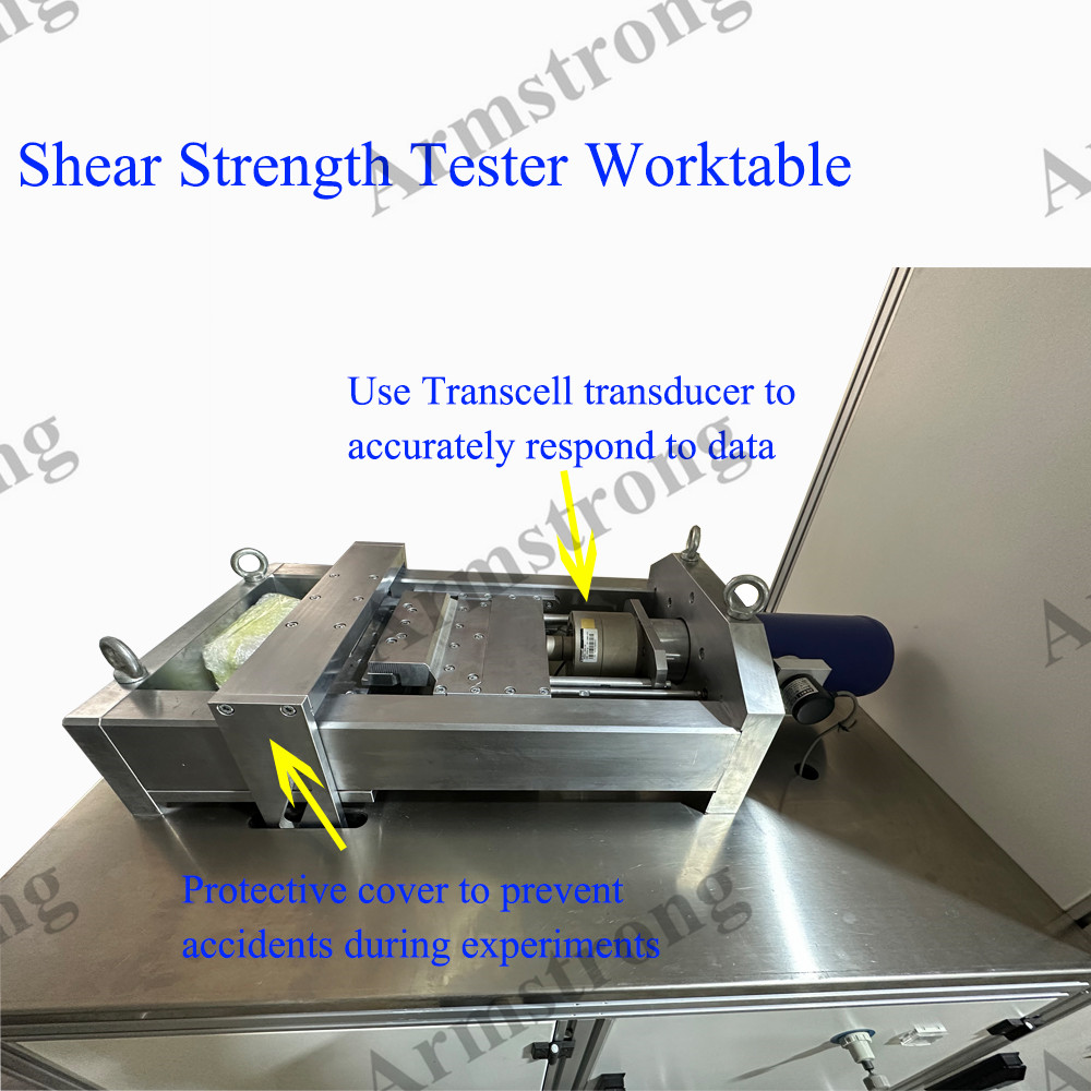
1. Sensor measurement area: including real-time shear force, maximum shear force, shear strength and shift display
A. Shear Force: Real time display of measured shear force
B. Max Shear Force: During the shear test, extract the max shear force of the current test.
C. Compression Pressure: the air pressure of the compression cylinder (unit: MPa) during the test.
D. Shear Strength: During the shear test, the shear strength is calculated in real time according to the test area of the test piece provided.
E. Shift Display: Measure the forward and backward position of scissors.
2. Condition indicator area: including home position, slow speed, tighten, cut down, forward and backward indicators.
A. Home Position indicator: Home position indication of shear arm (on the left)
B. Slow Speed indicator: After the test, the shear arm moves rapidly to the right and starts to move forward slowly after reaching the slow speed indicator light.
C. Tighten indicator: Indication when tightening cylinder extends.
D. Cut Down indicator: During the test, the shear arm moves to the far right, and when the cutting indicator light is on, it indicates that the test piece is cut.
E. Forward indicator: The shear arm moves to the right.
F. Backward indicator: The shear arm moves to the left.
G. Upper limit: Upper limit of tightening cylinder.
H. Lower limit: Lower limit of tightening cylinder.
3. Specimen Information area
A. File: File name of the data saved by the current test sample
B. Specimen Size: unit cm2
C. Storage Path: Data file storage path
D. File No.: When testing samples of the same batch, in order to save time, the system automatically increments the file name after the former file name. After each test, the file name automatically increases by 1. If you change the batch or rename, you can click the file serial number, clear the increment and restart counting.
4. Condition and Alarm area
A. Condition: Status display during equipment operation
B. Alarm: Abnormal display during equipment operation (flashing in case of alarm)
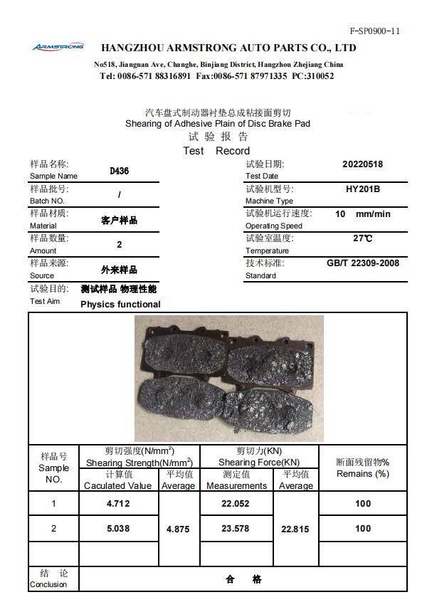
Test report sample